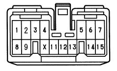
- Plug1.jpg (6.12 KiB) Viewed 1523 times
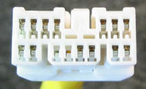
- Plug2.jpg (50.67 KiB) Viewed 1523 times
1: AMP
2: ILL+
3: ACC (switched +12v)
4: +B (permanent +12v - fed by Dome fuse via the amps)
5: MUTE
6: FL
7: FR
8: ANT
9: LL- (?)
10: (normally unused)
11: GND
12: S-GND (Common earth wire for the low level speaker wires)
13: BEEP
14: RL
15: RR
I'm not recommending you do this. Information purposes only

but here goes for a bit more clarification:
As per my previous post above. You can hardwire this system to a Standard ISO power plug: Orange wire = dimmer (ILL+), Blue (REM) = AMP + ANT (splice the 2 wires together if no separate antenna wire), Yellow = B+ (permanent +12v), Red = ACC (switched 12v). Black = GND. Check your Head Unit wiring diagram as Red & Yellow wires can sometimes be the other way round (premanent & switched live).
Speakers: Require a low-level signal the same as an aftermarket amp would. Your head unit ideally needs to have RCA outputs otherwise you will need the relevant adapters (high-low if using normal standard speaker wires) or splitter if only a pair of RCA outputs.
Connect 4 RCA's (I just chopped up a pair of standard RCA leads to provide the plugs and short length of wiring to splice in) to the factory loom wires: +ve wire of each RCA (centre pole)to the low-level (FR/FL/RR/RL) wires and all 4 Negative wires are then joined together and spliced to the S-GND wire (common/signal ground). You will not then use the standard ISO speaker plug.
This works as I have done it before. Alternatively if you want to reinstate the oem Toyota plug then you will need the correct adapter. I would generally prefer using the oem plug/adapter but the option is there.
Check you are getting a permanent live to the L-Y (Blue-Yellow) wire at the main amp plug.
Most of this is from memory. Check the factory loom wiring before cutting anything. The wiring diagrams should begin to make sense. Please make use of a multimeter to test as you go along.